 EN
EN
 AR
AR
 BG
BG
 HR
HR
 CS
CS
 DA
DA
 NL
NL
 FI
FI
 FR
FR
 DE
DE
 EL
EL
 IT
IT
 JA
JA
 KO
KO
 NO
NO
 PL
PL
 PT
PT
 RO
RO
 RU
RU
 ES
ES
 SV
SV
 TL
TL
 IW
IW
 ID
ID
 LV
LV
 LT
LT
 SR
SR
 UK
UK
 TR
TR
 MS
MS
 BE
BE
 HY
HY
 AZ
AZ
 KA
KA
 EO
EO
 LA
LA
 SU
SU
 TG
TG
 UZ
UZ
Агляд
Запыт
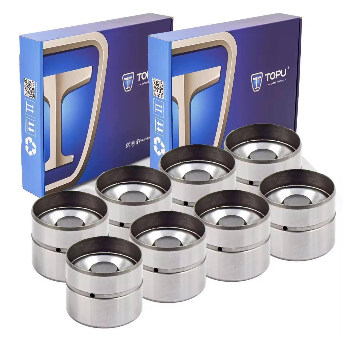
ПАРУЖНЫЯ ПРЫЗНАЦКІ
Апісанне праduktу
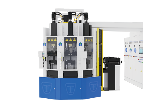
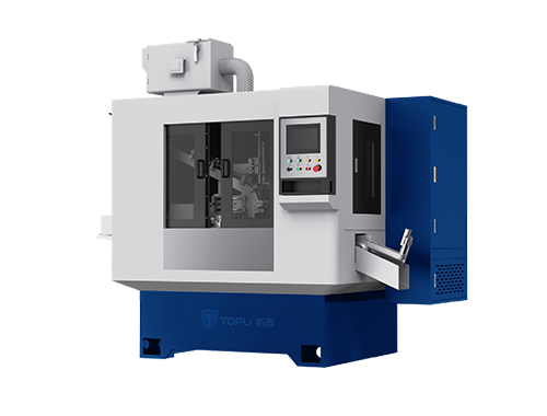
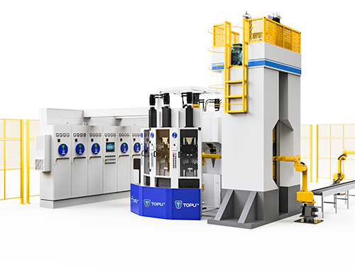
1. Асноўны працэс працягвання:
Кваліфікаваныя штыхты выяўляюцца з бака ў загрузчай касетцы. Робат-загрузчык перадaje штыхты на электрычную машыну для пазнейшага працягвання, дзе пачынаецца электрычнае працягванне. Пасля завяршэння электрычнага працягвання, робат-выгрузчык іх вымяняе і клае ў прес для валявання, што ў выніку выдае цяліну валя. Галоўная сістэма кантролю ўзgadoрднення гэтых дзеянняў ў парадку і непрырывна.
2. Раскладка праўяджання:
Шэсць электрычных машинаў для кулябкі ўсталяваныя ў двух секторах, сіметрычна злева і справа, з трыма машинамі злева і трыма справа. Рабочыя поўерхні электрычных машин для кулябкі спадзяюцца наруж у. Робат размяшчаны ў цэнтры сектораў, які выкарыстоўваецца для завантажэння і вывантажэння электрычных машин для кулябкі. Контейнеры для завантажэння размяшчаныя ў пралётах паміж двума секторамі. Гэта фармуе акружнасць з шасццю электрычнымі машинамі для кулябкі, адным прэсам і двума контейнерамі для завантажэння, з робатам, які знаходзіцца ў цэнтры акружнасці.
Кулябка:
Цэнтруванне захопа
Аўтаматычнае нульаванне бабка
50KVA двухфазны трансформатар, холостой ток <0.2A
Укомплектавана прыладай абараны ад згіну
Укомплектавана прыладай прадзярвы для кулябкі, нагрэvanня стага, кулябка з фіксаваным дызытанцыям, сегментацыя па параметрам і вучэнне сервамеханізма
Галоўнае кіраванне:
Храненне параметраў
Лічэнне вытвора
Падаўленне працэсу крывой
Сігналызацыя высоцы і нізкіх температураў
Дысплэй рабочага статусу
Аўтаматычны адключэнне ў разе зламу штампаўніка
Анлайн-дадаванне і адыманне штампаўнікаў
Загрузка:
Магнітнае сартаванне
Сартаванне па фаскам
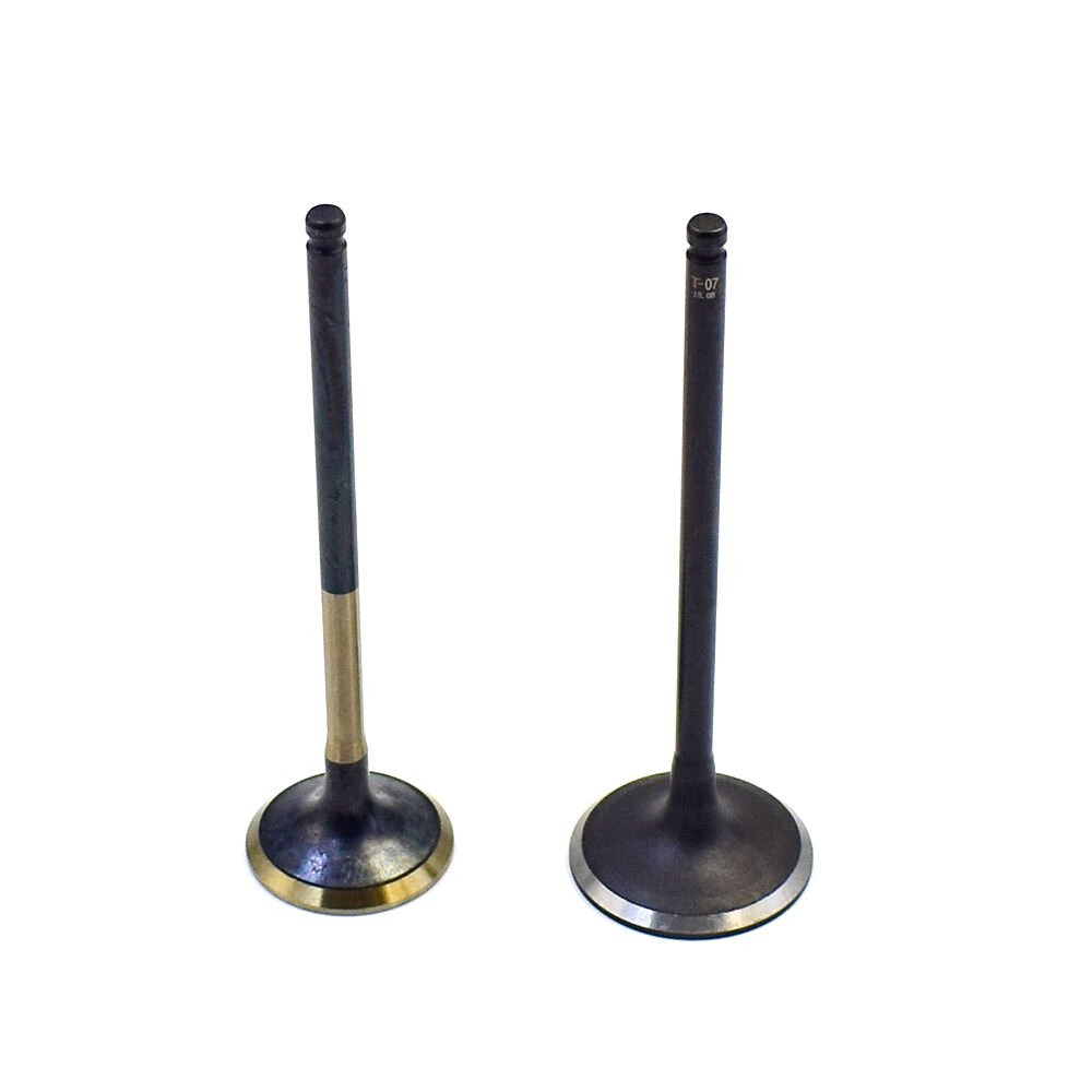
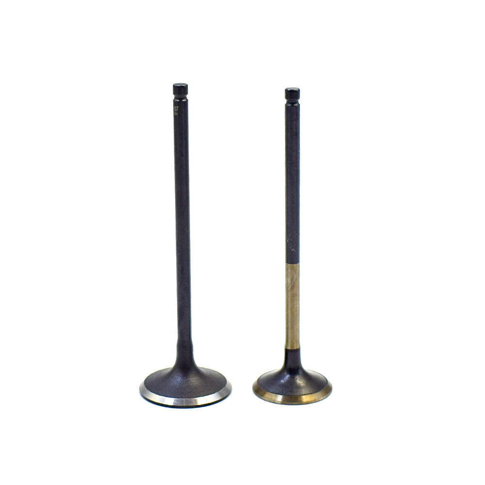
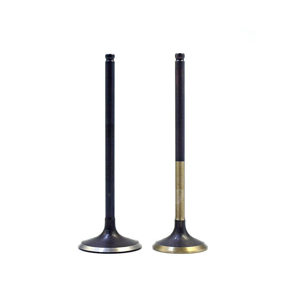
3. Матэрыял дэталі:
Парызавая форма ў сечэнні цыліндрычная, з дыяметрам ад ø5 да ø13, з толькай падлікам па стандартзе ISO h11.
Паверхневыя ўмовы: Халадна выцягнутыя, чашчавыя ці поліраваныя штыфты без альёю.
Шэрагаўасць паверхні: Ra 2.5
Умовы кancтавання: Паверхня канца стужкі павінна быць гладкай, плоскай і бяз аksідацыі. Канцавая паверхня павінна мець правільныя фармы зусіпку.
Матэрыял: Падыходзіць для усіх тыпаў сталі.
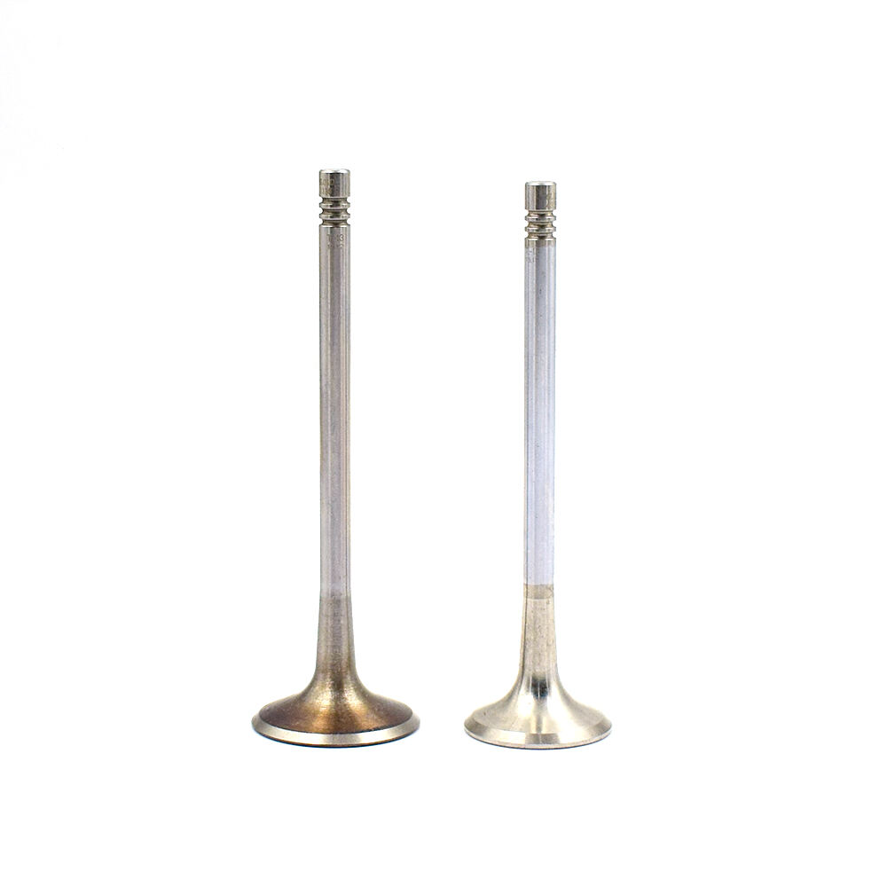
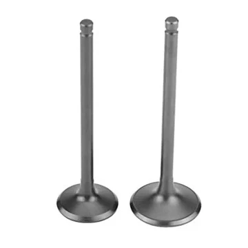
4. Прадуктыўнасць:
Хуткасць расшырэння напрамую ўплывае на цыкл працы і вынік. Хуткасць расшырэння абмежавана сплавам матэрыяла, дыяметрам стужкі, станам паверхні стужкі, формай часткі расшырэння і магчымасцю адпрацоўкі трансформата.
Дыяметр стужкі: Ds = 8.7mm
Паўная даўжыня стужкі: L = 300mm
Даўжыня без расшырэння: k = 120mm
Дапаможная час: t = 2c
Даўжыня расшырэння: L - k = 300 - 120 = 180mm
Хуткасць паднімання: v = 12мм/с
Хуткасць наковальні: v = 2мм/с
Час цыклу: Дыстынцыя паднімання / (Хуткасць паднімання - Хуткасць наковальні) + Дапаможны час = 180 / (12 - 2) + 5 = 23с