Overview
Inquiry
Related Products
Product Description
1. Basic Operation Process:
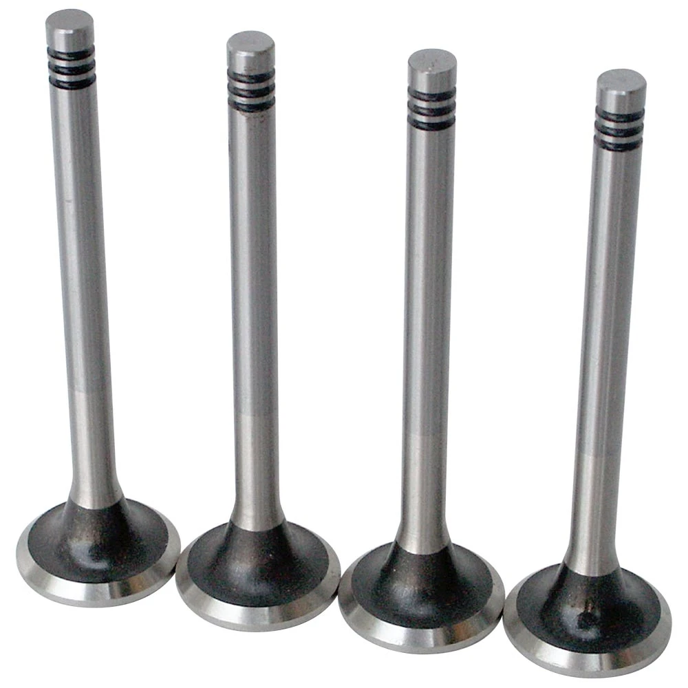
Qualified rods are selected from the hopper in the loading box. The loading robot delivers the rods to the electric upsetting machine, where the electric upsetting begins. After the electric upsetting is completed, the unloading robot removes them and places them into the press for forging, ultimately producing a valve blank. The main control system coordinates these actions in an orderly and continuous manner.
2. Production Line Layout:
Six electric upsetting machines are arranged in two sectors, symmetrically left and right, with three machines on the left and three on the right. The electric upsetting work surfaces face outward. A robot is placed at the center of the sectors, which is used for loading and unloading the electric upsetting machines. The loading boxes are placed in the gaps between the two sectors. This forms a circle with six electric upsetting machines, one press, and two loading boxes, with the robot located at the center of the circle.
Electric upsetting:
Clamp centering
Automatic zeroing of the anvil
50KVA two-phase transformer, no-load current <0.2A
Equipped with anti-bending device
Equipped with preheating for upsetting, rod heating, fixed-length upsetting, parameter segmentation, and servo ball screw return
Main control:
Parameter storage
Workpiece counting
Curve process display
High and low temperature alarms
Work status display
Fault upsetting machine automatic offline
Online adding and removing of upsetting machines
Loading:
Magnetic sorting
Chamfer sorting
3. Workpiece Material:
The cross-sectional shape is circular, with a diameter of ø5 to ø13, and dimensional tolerance according to ISO standard h11.
Surface condition: Cold-drawn, peeled, or polished oil-free rods.
Surface roughness: Ra 2.5
End surface condition: The rod end surface must be smooth, flat, and free of oxidation. The end surface should have a proper chamfer.
Material: Suitable for all types of steel.
4. Productivity:
The upsetting speed directly affects the work cycle and output. The upsetting speed is limited by the material alloy, rod diameter, rod surface condition, shape of the upsetting part, and transformer adjustment power.
Rod diameter: Ds = 8.7mm
Rod full length: L = 300mm
Unupset length: k = 120mm
Auxiliary time: t = 2s
Upset length: L - k = 300 - 120 = 180mm
Upsetting speed: v = 12mm/s
Anvil speed: v = 2mm/s
Cycle time: Upset length / (Upsetting speed - Anvil speed) + Auxiliary time = 180 / (12 - 2) + 5 = 23s

 EN
EN
 AR
AR
 BG
BG
 HR
HR
 CS
CS
 DA
DA
 NL
NL
 FI
FI
 FR
FR
 DE
DE
 EL
EL
 IT
IT
 JA
JA
 KO
KO
 NO
NO
 PL
PL
 PT
PT
 RO
RO
 RU
RU
 ES
ES
 SV
SV
 TL
TL
 IW
IW
 ID
ID
 LV
LV
 LT
LT
 SR
SR
 UK
UK
 TR
TR
 MS
MS
 BE
BE
 HY
HY
 AZ
AZ
 KA
KA
 EO
EO
 LA
LA
 SU
SU
 TG
TG
 UZ
UZ


