 EN
EN
 AR
AR
 BG
BG
 HR
HR
 CS
CS
 DA
DA
 NL
NL
 FI
FI
 FR
FR
 DE
DE
 EL
EL
 IT
IT
 JA
JA
 KO
KO
 NO
NO
 PL
PL
 PT
PT
 RO
RO
 RU
RU
 ES
ES
 SV
SV
 TL
TL
 IW
IW
 ID
ID
 LV
LV
 LT
LT
 SR
SR
 UK
UK
 TR
TR
 MS
MS
 BE
BE
 HY
HY
 AZ
AZ
 KA
KA
 EO
EO
 LA
LA
 SU
SU
 TG
TG
 UZ
UZ
Overview
Inquiry
Related Products
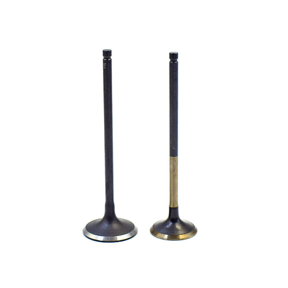
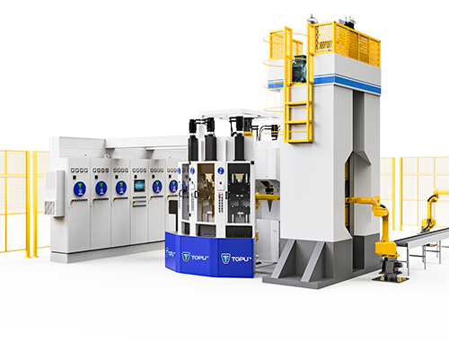
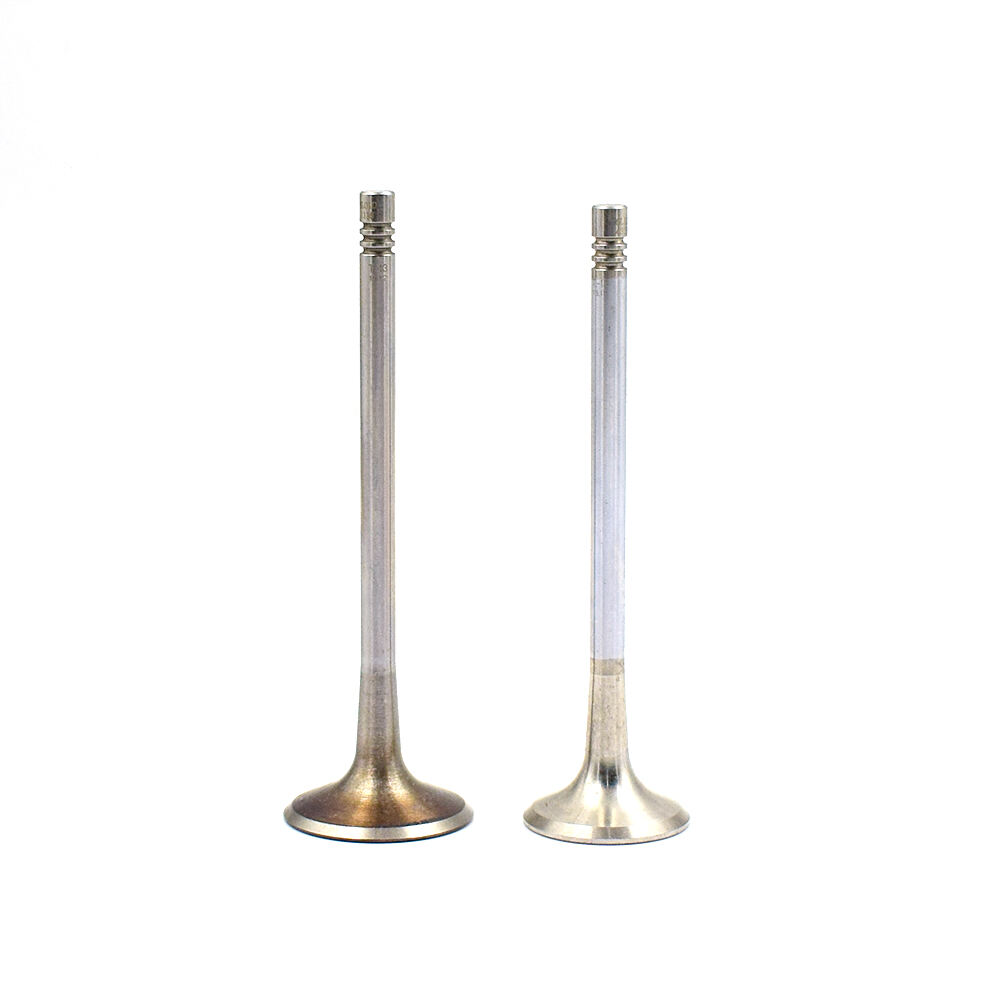
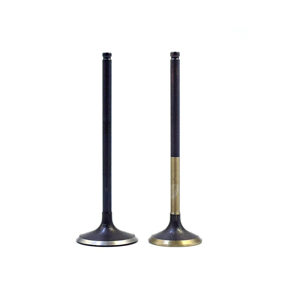
Product Description
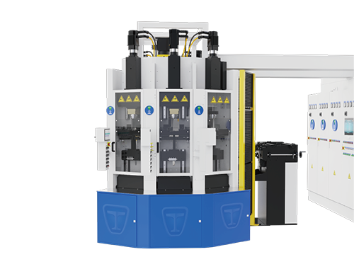
Mechanical Parts of the Pneumatic Electric Upsetting Machine:
1.1 Machine Body and Accessory Devices
The machine body is composed of five parts: the front panel, upper and lower support plates, frame, and cover plate. Inside the machine body, there are heating transformers and secondary wires.
1.2 Safety Protection Devices
The safety protection devices consist of two transparent protective doors, door magnets, and an induction switch. When the safety door is opened, the current upsetting machine will immediately stop working to protect personal safety.
1.3 Clamping and Automatic Centering Devices
The clamping and automatic centering devices consist of a pair of clamps, a pair of clamp jaws, a tension cylinder, and a start proportional valve. The tension cylinder simultaneously drives the left and right clamps to move towards each other to clamp the workpiece.
1.4 Anvil Retraction Device
The anvil retraction device consists of a servo motor, a precision planetary reducer, a set of ball screws, a set of sliding blocks, and a set of anvil pulling devices. The servo motor's power drives the ball screw via the planetary reducer, causing the sliding block to move up and down.
1.5 Hydraulic Upsetting Device
The hydraulic upsetting device consists of an independent hydraulic station, a heavy-duty cylinder, and a set of moving sliders. The independent hydraulic station directly drives the heavy-duty cylinder, which in turn drives the moving slider up and down.
1.6 Workpiece Anti-Bending Device
The workpiece anti-bending device consists of two adjustable cylinders and a pair of clamps. The two cylinders directly drive the two clamps to move to the appropriate position to prevent the valve from bending.
1.7 Cooling Water System
The cooling water system consists of three water circuits. The first circuit's cooling water enters the anvil electrode through the water inlet manifold, passes through the heating transformer, and flows out to the water outlet manifold. The other two circuits connect to the clamps on both sides. The entire system uses stainless steel components to prevent rust and clogging.
1.8 Pneumatic Device and Piping System
This equipment is equipped with the proportional pressure valve, solenoid valve, filter, and piping system needed for electric upsetting forming. The air source pressure should not be less than 4.5 kgf/cm².
Electrical Parts:
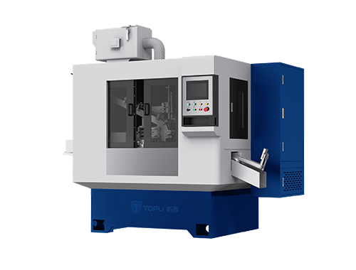
2.1 Electrical Control System
The electrical control system circuit diagram (see attached drawing) mainly includes: a programmable controller, output amplification isolation board, proportional valve, proportional amplification board, heating controller, silicon-controlled rectifier, heating transformer, and some protection components. The electrical control cabinet is independently installed for easy maintenance and repair.
2.2 Electric Upsetting Heating System
The electric upsetting heating system is located within the machine body and consists of a heating transformer, output copper connections, upper electrode copper plate, and clamp copper electrodes. The upper electrode and clamp electrodes are respectively connected to the two electrodes of the transformer, and the workpiece is heated by a large current passing through the two electrodes.
2.3 Monitoring System
The monitoring system of the upsetting machine includes real-time monitoring of cooling water flow rate, upper electrode temperature, hydraulic system oil temperature, workpiece processing temperature, and system air pressure. This comprehensive monitoring ensures that the upsetting machine always operates in a normal working state, preventing machine malfunction and reducing the scrap rate.
2.4 Button Box
The button box consists of buttons and a control panel. The buttons facilitate the operator's testing and trial operation of the machine. The control panel displays the current running status of the machine, such as the current workpiece processing temperature, anvil temperature, hydraulic oil temperature, cooling water flow rate, fault codes, and processing parameters.